Abstract:For the welding of copper in battery connector , pulse laser and continuous fiber laser were used to laser welding testing. For pulse laser , process parameters of peak power , pulse width and focal distances were carried to orthogonal ...
Contact Us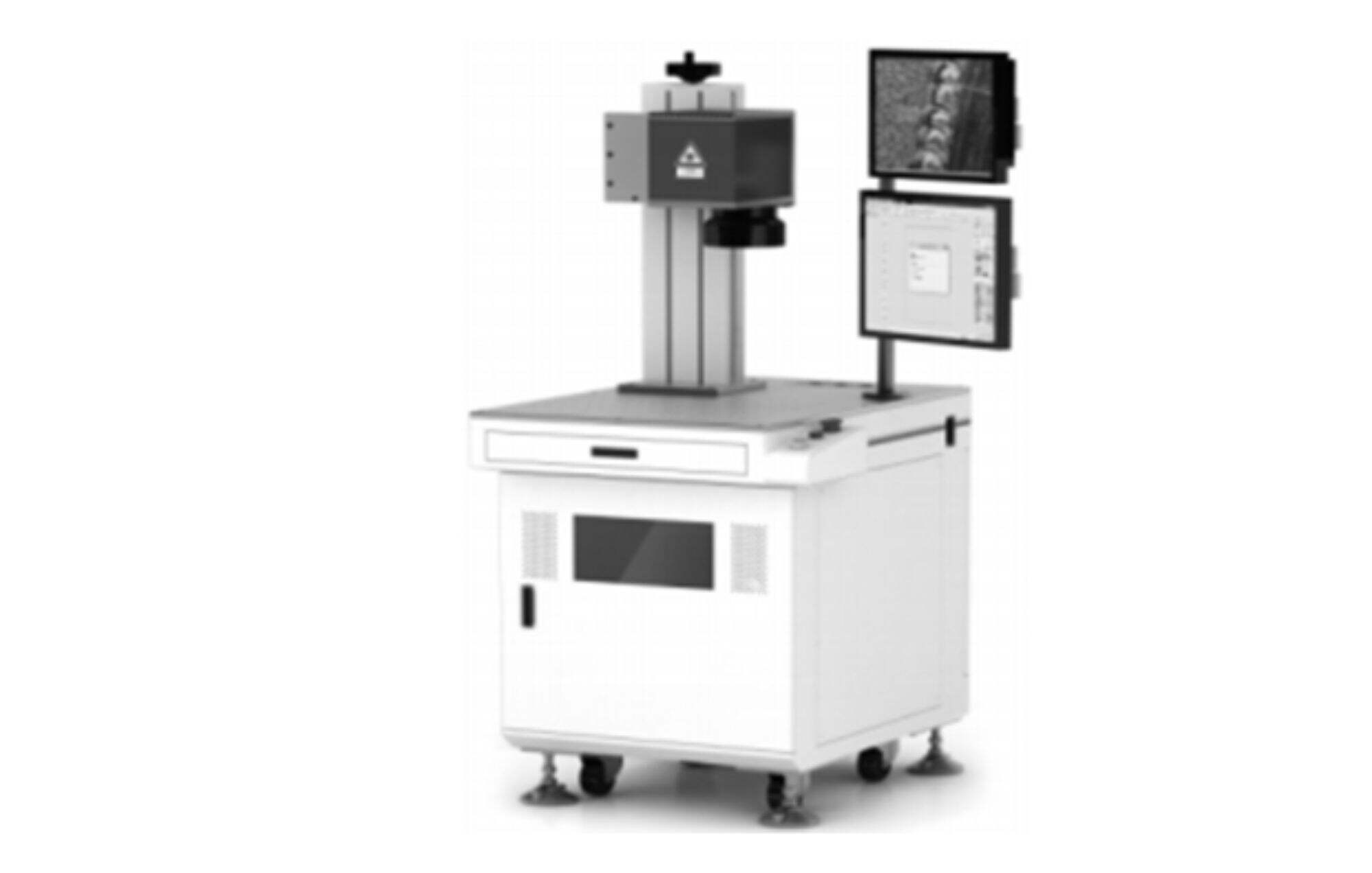
Abstract:For the welding of copper in battery connector , pulse laser and continuous fiber laser were used to laser welding testing. For pulse laser , process parameters of peak power , pulse width and focal distances were carried to orthogonal experiments , and obtained maximum shear force of 28N. For continuous fiber laser , process parameters of power、welding speed and focal distances were carried to orthogonal experiments , and obtained maximum shear force of 58N. The appearance of spots showed that welds inner of welded by pulse existed pore. Oppositely , welds inner of welded by continuous fiber laser bad no pore , which was useful for improving the shear force.
Keywords :copper ; laser welding; orthogonal experiments ; process parameter
0 introduction
Purple copper possesses advantages such as good heat conduction, excellent electrical conductivity, and ease of processing and shaping. It is extensively used in electrical wires and cables, hardware, and electronics manufacturing.Every unit within a mobile phone requires electric power to operate, such as the camera module, screen, speaker, memory, circuit board, etc. The battery is generally fixed in a specific area and needs a connector to link it with these components to form a conductive path for power supply. Purple copper is the most commonly used material for mobile phone battery connectors.The current mode of welding purple copper connector plates is mainly resistance welding. Large currents from positive and negative electrodes melt the copper connector plate. As the electrodes separate, the material cools to form a weld seam. While the structure of this welding device is simple and its operation is practical and convenient, the positive and negative electrodes used in resistance welding tend to wear out and breakdown, necessitating a halt in the production line for replacement, thus reducing production efficiency.
Laser welding, which uses lasers as its heat source for processing, has the advantages of small heat-affected area, high welding strength, non-contact with the workpiece, and high production efficiency. It has been extensively applied in the welding of materials such as stainless steel, aluminum alloy, nickel alloy, and so on.Purple copper has a high reflectivity of 97% or more to lasers, which necessitates an increase in laser power to compensate for the lost laser energy due to reflection, resulting in a significant waste of laser energy.Simultaneously, changes in the surface condition of the purple copper can affect the changes in copper's reflectivity to the laser, greatly increasing the instability of the welding process.To improve the laser weldability of copper, scholars have conducted extensive research on the copper surface, such as laser etching on the copper surface or coating with graphite, to increase the laser absorption rate of copper. While this method has improved the weldability of copper, it has also added to the production process and increased production costs.
The article employs the use of both pulsed lasers and continuous fiber lasers to conduct process optimization experiments on purple copper battery pole pieces, providing a reference for actual production.
1 Welding experiment
1.1 Experimental materials
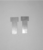
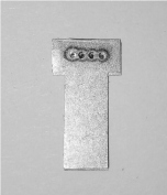
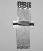
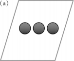
The upper layer of the experimental material is purple copper, with a thickness of 0.2 mm. The lower layer material is nickel-plated purple copper, with a thickness of 0.2 mm. The chemical composition of the two layers of material is shown in Table 1.The materials are cut into lengths and widths of 20mm x 6mm, as shown in Figure 1(a). Overlap welding experiments are conducted, requiring a welding area of 4mm x 0.5mm, as shown in Figure 1(b).After the welding is completed, a shear force test is carried out. The lower layer material is bent 180 degrees along the weld, and a shear force test is conducted, as shown in Figure 1(c).The shear force test uses a microcomputer-controlled electronic universal testing machine, model WDW-200E. The upper and lower ends of the product are clamped with a fixture, and the stretching speed is 50mm/s.
Tab.1 Chemical composition of testing materials( mass fraction/%)
|
Material |
Cu |
P |
Ni |
Fe |
Zn |
S |
|
Purple copper |
99.96 |
0.000 7 |
0.000 2 |
0.000 8 |
0.000 9 |
0.000 9 |
|
Nickel-plated purple copper |
99.760 |
0.000 5 |
0.200 0 |
0.000 6 |
0.000 9 |
0.000 8 |
|
(a) |
(b) |
(c) |
|
(a) Welding materials Fig.1 Welding method and shear force testing |
||
1.2 Welding equipment and methods
The welding experiment uses a 150W quasi-continuous pulsed fiber laser and a 1000W continuous fiber laser produced by Wuhan Raycus Company. The average power of the quasi-continuous pulsed fiber laser is 150W, the peak power is 1500W, and the pulse width is 0.2mm~25 ms. The electro-optical conversion efficiency of the fiber laser reaches more than 30%, which can get higher laser output power,also, the fiber laser has good beam quality, the diameter of the laser fiber is 0.05mm, the focus distance of the external collimating mirror portion is 100mm, and the focus distance of the focusing lens is 200mm, The laser focus spot is small, and the theoretical minimum spot can reach 0.1mm,the impact of a laser with high power density on the surface of copper material can rapidly raise the temperature of the copper material. As the temperature rises, the material's absorption rate of the laser also quickly increases. Therefore, using a fiber laser to weld copper materials can to some extent overcome the issue of high reflection of copper to the laser. The welding experiment platform is shown in Figure 2 above.
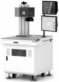
Fig.2 Welding experimental platform
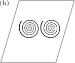
Each pulse from the quasi-continuous pulse fiber laser forms a welding spot, suitable for pulse spot welding. The schematic diagram of the welding spot is shown in Figure 3(a) above.The average power of the 1000 W continuous fiber laser is 1000 W, with no peak power, making it very suitable for continuous seam welding. Welding spots can be formed by operating in a spiral way as shown in Figure 3 (b) above.
 |
 |
|
(a) Pulse solder joint formed by quasi-continuous pulse fiber laser Fig.3 Schematic diagram of welding spots |
|
2 Experimental results and analysis
2.1 Optimization of pulse laser welding process
The main welding process parameters for quasi-continuous pulse laser welding are peak laser power, pulse width, and defocusing amount. A three-factor three-level orthogonal experiment is conducted on these three process parameters, and the results of the orthogonal experiment and tensile test are shown in Table 2.Laser peak power primarily affects the weld spot melting depth. As the peak power increases, the melting depth will also increase. However, when the peak power is too high, the material is prone to vaporization, causing material spattering and leaving pores inside the weld seam.Pulse width primarily affects the size of the weld spot, with the size of the weld spot increasing as the pulse width increases.The defocusing amount is the distance between the laser focus and the workpiece surface. If the laser focus is beneath the surface of the workpiece, it is considered negative defocusing. In this situation, it is easy to obtain a weld seam with a deeper melting depth,As the material is quite thin at 0.2mm, if the melting depth is too large, it can easily lead to the lower material being penetrated, which in turn could reduce the shear force of the weld spot,In the text, positive defocusing is used for welding (i.e., the laser focus is above the surface of the workpiece). The size of the defocusing amount determines the size of the light spot; as the defocusing amount increases, the light spot enlarges, reducing the power density acting on the surface of the material, and consequently decreasing the welding melt depth.When the peak power is 1400W, the peak power is too high, making it easy to generate spatter. This material loss leads to a decrease in the shear force of the weld spot.When the peak power of the laser is 1200W, the shear force of the weld spot is generally high. When the peak power of the laser is 1200W, the pulse width is 8ms, and the defocus amount is 1mm, the maximum shear force can reach 28N.
Tab.2 Orthogonal experiment and result of pulse laser
|
Number |
Peak power/W |
Pulse width/ms |
Defocus amount/mm |
Shear force/N |
| 1 | 100 | 4 |
0
|
13
|
| 2 | 100 | 6 |
1
|
15
|
| 3 | 100 | 8 | 2 |
16
|
| 4 | 1200 | 4 | 2 |
25
|
| 5 | 1200 | 6 |
0
|
23 |
| 6 | 1200 | 8 |
1
|
28 |
| 7 | 1400 | 4 | 2 | 22 |
| 8 | 1400 | 6 | 1 | 21 |
| 9 | 1400 | 8 | 0 | 20 |
2.2 Optimization of continuous fiber laser welding process
The main process parameters of continuous fiber laser welding are laser average power, welding speed (the speed of the laser running the spiral line), and defocus amount (as with quasi-continuous pulse laser welding, positive defocus is used for the experiment). Orthogonal experiments and tensile test results with these three parameters on three levels are shown in Table 3.The average power of the laser affects the melting depth and the heat affected zone of the weld seam. As the power increases, the melting depth will increase, and the heat affected zone will also enlarge, making it easy to produce overburn, resulting in a decrease in tension.The welding speed will have an impact on the melting depth and the heat affected zone of the weld seam. As the welding speed increases, the melting depth of the weld point decreases, and the heat affected zone also decreases.The size of the defocus determines the size of the light spot. As the defocus increases, the light spot becomes larger, and the power density acting on the surface of the material decreases, which will reduce both the welding melting depth and the heat affected zone.When the average power is 500 W, the shear force is generally small. This is because the average power of the laser is low, the melting depth of the welding point is low, leading to a low shear force. When the average power is 700 W, the average power of the laser is too high,this results in a too large heat affected zone. When testing shear force, it first tears from the heat affected zone, which causes the shear force of the welding point to be low.When the average power of the laser is 600 W, the shear force of the welding point is generally higher. When the average power of the laser is 600 W, and the welding speed is 150 mm/s, with a defocus of 0mm, the shear force reaches a maximum of 58N.
Tab.3 Orthogonal experiment and result of fiber laser
|
Number |
Average power/W |
Welding speed/(mm/s) |
Defocus amount/mm |
Shear force/N |
| 1 | 500 | 100 | 0 | 33 |
| 2 | 500 | 150 | 1 | 35 |
| 3 | 500 | 200 | 2 | 32 |
| 4 | 600 | 100 | 2 | 49 |
| 5 | 600 | 150 | 0 | 58 |
| 6 | 600 | 200 | 1 | 53 |
| 7 | 700 | 100 | 2 | 44 |
| 8 | 700 | 150 | 1 | 43 |
| 9 | 700 | 200 | 0 | 40 |
2.3 Comparative analysis of appearance
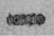
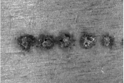
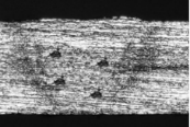
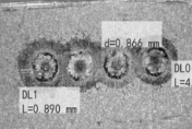
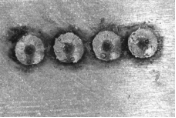
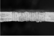
In order to analyze the tensile difference in shear force between pulsed laser and continuous fiber laser welding of copper, the appearance of the welding spot is analyzed. By observing the welding spot with an electron microscope, when the peak power of the pulsed laser is 1200 W, the pulse width is 8 ms, and the defocus is 1 mm, there is partial spattering on the surface of the welding spot, leaving pits on the surface, as shown in figure 4(a).On the back of the welding point, obvious holes can be seen in some parts, as shown in Figure 4(b). After cutting open the weld, polishing, grinding, and corroding, a magnifying glass is used to test the cross-section of the weld, as shown in Figure 4(c),there are pores inside the weld, which is due to the high reflectivity of copper, requiring high peak power to weld. However, the high peak power causes some elements to vaporize easily, generating pores which will reduce the shear force of the welding point.When welding with a continuous fiber laser, when the average laser power is 600 W, the welding speed is 150mm/s, and the defocus is 0mm, the surface of the welding point is uniform and consistent, with no pits or spatter generated, as shown in Figure 4(d).There are no holes or obvious defects on the back of the welding point, as shown in Figure 4(e). Using a magnifying glass to test the cross-section of the weld from continuous fiber laser welding, as shown in Figure 4(f),The weld is free of pores and is composed of bundles of weld seams, which is due to the use of a certain laser power to perform spiral welding in continuous laser welding. A lower laser power is utilized, and by heat accumulation, the top and bottom materials are melted. Weld consistency is good, with no formation of pores or other defects, resulting in greater shear force compared to pulse laser welding.
|
(a) |
(b) |
(c) |
|
(b) |
(e) |
(f) |
|
(a)Pulse laser welding surface Fig.4 Appearance of spots |
||
Pulse laser and continuous fiber laser are used separately to weld phone battery connectors, and resistance testing is performed.After pulse laser welding, the tested resistivity is 0.120Ω·mm2/m, higher than the original resistivity of copper which is 0.018 Ω·mm2/m. This is due to the increase in resistivity caused by the presence of pores inside the welding point.After continuous fiber laser welding, the tested resistivity is 0.0220 Ω·mm2/m, close to the resistivity of the parent material, copper, thereby meeting practical production requirements.
3 Conclusion
A 150 W quasi-continuous pulse fiber laser and a 1000 W continuous fiber laser are used separately for welding experiments on copper, in order to conduct process optimization experiments.When the peak power of the pulse laser is 1200 W, the pulse width is 8 ms, and the defocusing amount is 1mm, the maximum shear force achieved is 28N. When the average power of the continuous fiber laser is 600 W, the welding speed is 150mm/s, and the defocusing amount is 0mm, the maximum shear force achieved is 58N.
An analysis of the weld point appearance and cross-section shows that the pulse laser weld spot has splatters on the surface and the weld seam has pores inside. The continuous fiber laser weld spot has a consistent and uniform surface with no pores inside the spot, which improves the shearing force of the weld point. This provides valuable reference for the choice of laser light source required in practical production.
 EN
EN
 AR
AR CS
CS NL
NL FR
FR DE
DE IT
IT JA
JA KO
KO PL
PL PT
PT RU
RU ES
ES UK
UK TH
TH TR
TR