1.1 Focus plane 1.1.1 Focus Definition:The energy distribution of the beam cross-section is as shown in the left figure, and the longitudinal section of the beam energy distribution is also as shown in the left figure. The beam is output from th...
Contact Us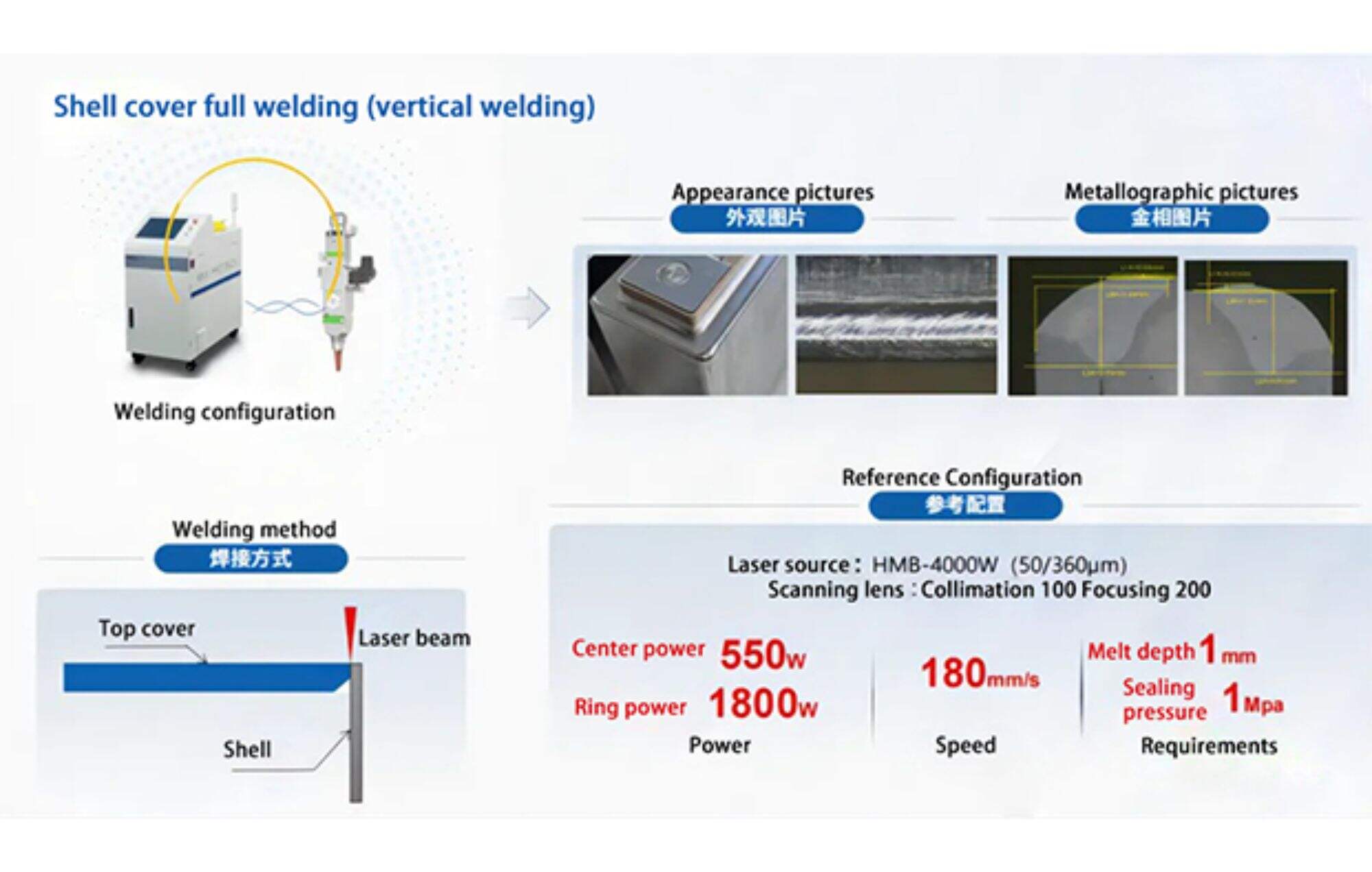
1.1 Focus plane
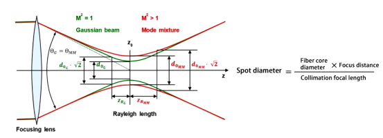
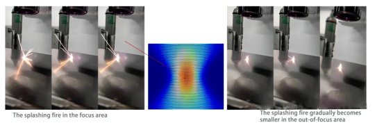
1.1.1 Focus Definition:The energy distribution of the beam cross-section is as shown in the left figure, and the longitudinal section of the beam energy distribution is also as shown in the left figure. The beam is output from the laser, and after passing through the collimating focusing lens, it will focus at a certain position, forming a beam waist. This point has a feature that the spot is the smallest, and the energy density of the beam is the highest, which is the focal point.
The distribution of laser energy is strictly symmetrical along the focal plane. Through the physical phenomenon of laser interacting with materials, one can determine the energy boundary, thus determining the central position of the focus point.
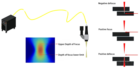
1.2 The basis for judging the boundary coordinates:The boundary between areas with spatter and without spatter; The length and brightness of the upper limit plasma flame (firelight) and the corresponding state of the lower limit plasma flame (firelight), with the median value taken; The plane where the sound is loudest and the physical reaction is most intense.
1.3 How to determine the focal plane:
1.3.1. The first step is to set the benchmark
Coarse positioning:
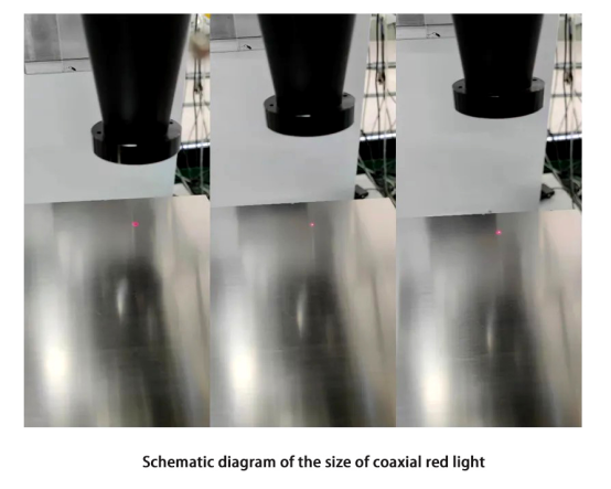
If you are unsure about the approximate location of the depth of focus, you can first move the Z axis to where the spot of the coaxial red light is smallest, which is generally near the depth of focus; Find the smallest guide spot, and then look for the upper and lower boundaries of the focal point energy.
Precautions:
With the same external light path configuration, different powers will result in different depths of focus. Therefore, when determining the focal point, the power should be set as low as possible to make it easier to set the boundaries.
1.3.2 Step 2 Pulse dot method - check the solder joints
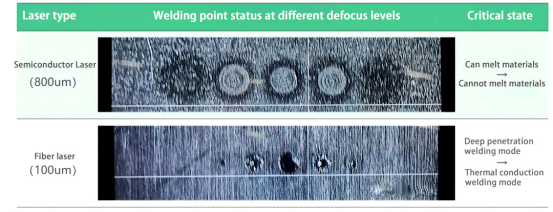
Search for the coordinates of the critical state of positive and negative defocus, the midpoint of the two coordinates is taken as the focus coordinates.
Pulse dotting method - watch the sparks
Of course, you can also listen to the sound, as for which feature to choose for judgment, it depends on the situation of the onsite laser and material, and whichever is more convenient for judgment should be chosen.
Also note:
1) Ensure not to emit light continuously at the same position (hitting on the smooth material surface and the welding point where the characteristic differences are large will cause significant misjudgment);
2)The material used to find the focal point must be flat, without height changes, and the surface must be clean;
3)Find the focal point multiple times and take the average value to reduce the error.
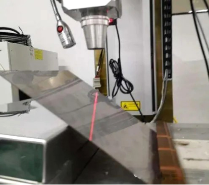
1.3.3 Determining the focal plane using the oblique line method
Notes on slashing:
General steel plate:
1) For semiconductors, use around 500W or less; for fiber optics, around 300W will suffice;
2)The speed can be set between 80-200mm/s;
3)The larger the bevel angle of the steel plate, the better, preferably around 45-60 degrees; the midpoint is located at the coarse positioning focus of the smallest and brightest guide spot.
Then start marking the line. What effect should the marking achieve? Theoretically, this line will symmetrically distribute around the focal point, and the trajectory will undergo a process of increasing from small to large and then decreasing again, or decreasing from large to small and then increasing again.
For semiconductors, look for the thinnest point. The steel plate will turn white at the focal point with obvious color characteristics, which can also serve as a basis for locating the focal point. Secondly, for fiber optics, try to control the backside to be slightly translucent. If it's slightly translucent at the focal point, that indicates that the focal point is at the midpoint of the backside's slight translucent length.
1.3.4 Spiral dotting: galvanometer to find the focus
When single-mode is paired with galvanometer, it is sometimes difficult to find the critical point of physical features because of the excessively large magnification ratio. Therefore, a method of marking a spiral line, using a more dense energy input, is derived to determine the focal point.
1)Create a spiral line within the galvanometer frame and center it.
Set the helix parameters:
•Starting point radius 0.5mm
•Ending point radius 1.5mm
•Spiral pitch 0.5mm;
(*The end point radius of the spiral line should not be set too large, generally 1mm~2mm is appropriate.)
2)The welding speed should generally be set to ≥100mm/s. If the speed is too slow, the spiral wire welding effect is not obvious. The recommended speed is 150mm/s.
1.4 Welding speed
The laser welding system is composed of a laser, transmission fiber, collimating focusing head or galvanometer, etc. The light that comes out of the fiber is divergent and needs to be turned into parallel light by a collimating lens, and then converted into a focused state (magnifying glass effect) through a focusing lens. The key parameters during laser process debugging include: speed, power, defocusing amount, and protective gas, etc. Generally, the process report provided by process engineers when testing in the lab primarily contains the above four parameters, as well as the chosen laser model configuration.
1.4.1 Effect of speed on welding quality: line energy
Generally speaking, before deciding what parameters to choose for a workpiece, it is necessary to first determine the processing speed. This requires communication with the customer to meet their demands, such as production rhythm requirements and output demands. From these, you can approximately deduce the required speed, and then perform process debugging on this basis.
During the laser welding process, the welding speed directly affects the line energy density of the laser beam, which significantly affects the size of the weld seam. Meanwhile, under different welding speeds, the flow pattern of the melt pool during the laser welding process also varies.
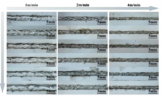
Increasing the speed of a single fiber laser: This will cause line energy to decrease, and the weld seam will change from thick to thin. It will transition from deep penetration welding to conduction welding until no welding mark is present due to lack of fusion.Generally, the speed is not adjusted too much. For high-reflective materials, if there is a lot of segment welding or lack of fusion, slowing down can solve some of the issues. This includes reducing the heat-affected zone and line energy for some structural parts with plastic pieces at the edges or in layered welds by increasing the speed.
Pulse welding: speed affects the overlap rate;
Continuous laser welding: The core principle of how speed impacts welding is that it affects line energy distribution and therefore, the duration of laser action. This in turn leads to varying levels of metallographic fusion depth and width. The rule of influence is illustrated in the image below:
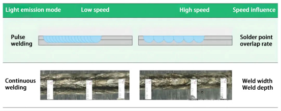
The fusion width decreases as the welding speed increases; the fusion depth also decreases as the welding speed increases; increasing the speed can to a certain extent reduce defects like undercuts and spatter.
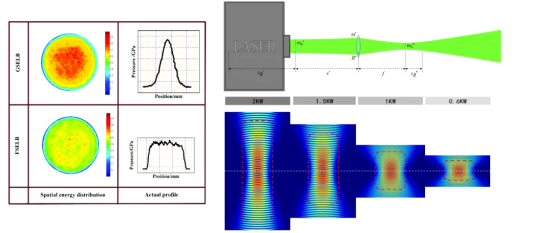
1.5 Welding power
Laser welding energy input is usually represented by energy density (laser power divided by the area of the spot, in units of w/cm²) and heat input (laser power divided by welding speed, in units of w/cm²). The former describes the intensity of the laser energy in the spatial range, while the latter describes the cumulation of laser energy over time.
The simple relationship between power, fusion depth, and fusion width is as shown in the image. Generally speaking: the larger the power, the fusion depth and width will increase with the power. Laser welding has an energy threshold. Below this threshold, it's called heat conduction welding, above it, it is called deep penetration welding. The difference is that deep penetration welding has a keyhole.
Common defects caused by insufficient power include: false welding, shallow fusion depth, and unclear welding marks; defects due to excessive power include: welding penetration, large spatter, wavy edges, and undercuts.
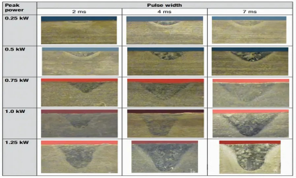
The relationship between power and melt depth and width: The greater the power, the greater the melt depth and width.
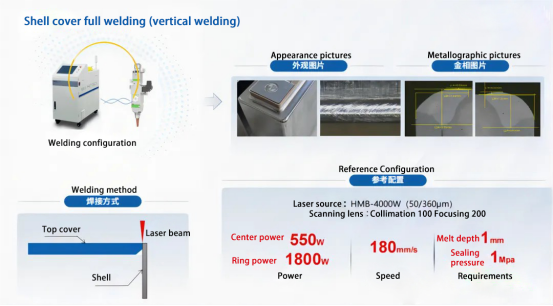
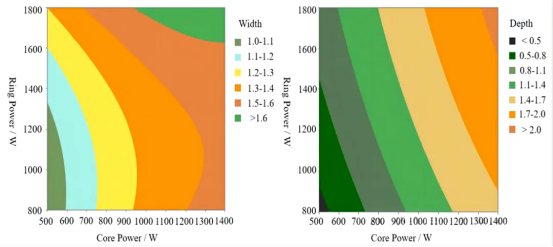
1.5.1 Ring-shaped spot:
The inner ring laser is mainly responsible for the fusion depth, as the power increases, the fusion depth increases.
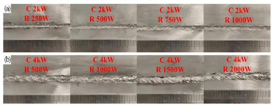
The outer ring laser has a smaller impact on the fusion depth and mainly affects the fusion width. As the power of the outer ring increases, the appearance of the weld seam becomes smoother and the fusion width increases.
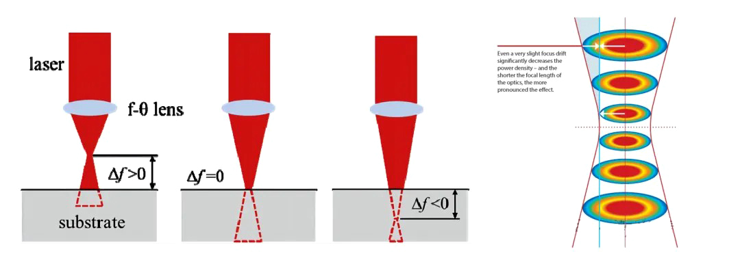
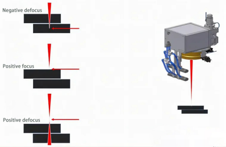
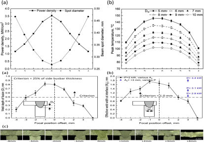
1.6 Defocus
Defocus is the distance between the laser focal plane and the surface of the workpiece to be welded. When the focal plane is above the surface of the workpiece, it is positive defocus; when the focal plane is below the surface of the workpiece, it is negative defocus. Naturally, when the focal plane is on the surface of the workpiece, the defocus is zero. Defocus is an important parameter in laser welding. Since the laser beam is focused into a focal spot to converge energy for welding by the lens inside the laser head at the focal length, therefore, from an optical point of view, changing the defocus of laser welding essentially changes the action spot area of the laser beam, thereby changing the laser power density.
Generally, when a process window is specified, a defocus range needs to be set, mainly for workpieces with high reflectivity surfaces, such as stainless steel, aluminum alloys, etc. Because these materials have mirror-like surfaces, if the defocus is too large, the unit energy will be too low to quickly melt the material surface, causing a certain amount of laser energy to reflect back and damage the lens of the welding head and the end face of the fiber.
At the same time, after selecting the fiber core diameter, if the gap between the workpieces is too large, and there may be a situation where the laser leaks over the seam, defocus can be used as a remedy to make the spot larger, thereby increasing the heated area and ensuring the molten pool covers the seam to prevent leakage of light.
Defocusing is usually chosen to be positive, and neither the focal point nor negative defocusing is selected because: the laser energy is mainly concentrated in the center of the focal spot. When the focal point is on the surface or inside the workpiece, the laser power density inside the molten pool is too high, which can easily cause welding splatter, rough weld surface, and unevenness.
The relationship between defocus and melting depth and width:
The depth of fusion decreases as the defocus increases, and the depth of fusion with negative defocus is greater than that with positive defocus; the width of fusion increases first and then decreases as the defocus increases.
1.7 Shielding gas
Shielding gas: There are many types of shielding gases. In industrial production lines, nitrogen is often used to control costs. In laboratories, argon is the main choice, but helium and other inert gases are also used, usually in special circumstances. The three most commonly used are nitrogen, argon, and helium.
Because laser welding is a process of high-temperature vigorous reaction, where metal melts and evaporates, metal is very active at high temperatures. Once it encounters oxygen, a violent reaction will occur, characterized by a large amount of spattering, and a rough and uneven weld surface. Therefore, the purpose of the shielding gas is to create an oxygen-free environment within a small range (near the molten pool) to prevent violent oxidation reactions from causing poor welds and rough appearance.
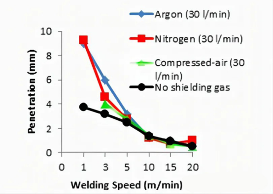
1.7.1 Effects of different protective gases
Metal vapor absorbs laser beams and ionizes into a plasma cloud. If there is too much plasma, the laser beam is consumed to some extent by the plasma. The shielding gas can disperse the metal vapor plume or plasma cloud, reducing its shielding effect on the laser and increasing the effective utilization of the laser.
At the same time, the shielding gas is also ionized by the high-energy laser. Due to differing ionization energies, different shielding gases will have different shielding effects on the laser.
According to experimental research, the ranking of ionization energy is: Helium > Nitrogen > Argon.
• Helium is the least likely to ionize under the action of a laser, and it has the smallest impact on the welding process.
• Argon has low reactivity and is an inert gas. It does not react with the material and is commonly used in laboratories.
• Nitrogen is a reactive gas because it can react with metal materials. It is generally used in situations where there are no high strength requirements, especially by production line companies considering cost.
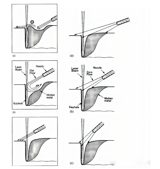
1.7.2 Effect of blowing protective gas at different angles
How to apply side blowing shielding gas?
• The angle and height of the side blowing shielding gas directly affect the coverage area of the shielding gas and the position at which it acts on the molten pool keyhole;
• Generally, different pipe diameters and flow rates of shielding gas should be matched according to the size of the welding molten pool to ensure the protective effect;
• The best angle for the shielding gas is 45-60°, which can effectively enlarge the keyhole opening and reduce spattering.
Side Blowing Shielding Gas
Advantages: It is beneficial for dispersing plasma, and blowing from front to back can effectively suppress spattering.
Impact: It may lead to an increase in porosity.
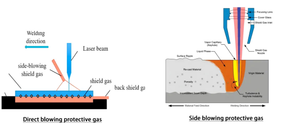
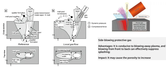
Direct Blowing Shielding Gas
Advantages:
• Direct blowing can effectively ensure the coverage area of the shielding gas over the molten pool, thus providing good protection;
• Direct blowing is simple to use and requires no adjustments, though attention should be paid as weld slag on the copper nozzle can interfere with the direction of the shielding gas flow, and turbulence can affect the effectiveness of the shielding gas.
Impact: Direct blowing can also effectively widen the keyhole opening, but excessive shielding gas flow can lead to an increase in porosity.
 EN
EN
 AR
AR CS
CS NL
NL FR
FR DE
DE IT
IT JA
JA KO
KO PL
PL PT
PT RU
RU ES
ES UK
UK TH
TH TR
TR