Hydrogen fuel vehicles are one of the main technical paths for the development of new energy vehicles in China. Due to their advantages such as strong endurance, low noise, and zero emissions, they are considered to be the ultimate direction for the development of new energy vehicles.Fuel cells are the main power source of hydrogen energy vehicles and a key factor affecting the performance of the vehicle. The bipolar plate is one of the main components of the fuel cell.Stainless steel is suitable for large-scale mass production of fuel cell bipolar plates due to its excellent stamping performance,high electrical conductivity, low price, diverse manufacturing methods, and good mechanical properties.
The welding of stainless steel sheets is a key process in the manufacturing process of fuel cell bipolar plates.When arc welding is used for welding, the heat input is relatively large, which can easily cause large welding deformations, which is not conducive to the welding of stainless steel sheets.This article uses fiber laser to conduct welding research on 1 mm thick 304 stainless steel sheets, explores the effects of different process parameters on weld formation and welding defects, and analyzes the microstructure and mechanical properties of joints under different specifications, for laser welding of 304 stainless steel. Provide guidance on practical engineering applications of thin plates.
1 Test materials and methods
The test material is a 1 mm thick cold-rolled 304 stainless steel sheet, and its chemical composition is shown in Table 1.Figure 1 shows the base metal structure of stainless steel, which is mainly austenite. There is an obvious rolling direction, and a small amount of ferrite structure remains between the austenite layers.
Tab.1Chemicalcompositionof 304stainlesssteel(wt%)
|
C |
Mn |
Si |
S |
P |
Cr |
Ni |
Fe |
|
0.027 |
1.6 |
0.36 |
0.002 |
0.01 |
18.5 |
11.6 |
余量 |
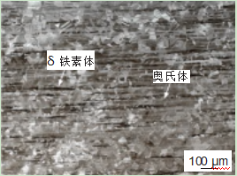
Fig.1 Microstructureof 304stainlesssteelbasemetal
The welding equipment is YLS-10000 fiber laser.The maximum output power of the laser is 10 kW,the focal length is 300 mm, the output wavelength is 1070 nm, and the spot diameter at the focus is 0.72 mm.Use different laser power P, welding speed v and beam defocus amount D to weld the plate, and analyze
the impact of different process parameters on forming. Argon gas was used for protection during the welding process,and the gas flow rate was 15 L/min.After welding, wire cutting was used for sampling. After grinding and polishing,FeCl3 reagent was used for corrosion. A stereo microscope was used to observe the macroscopic morphology of the weld section, and a metallographic microscope was used to observe the microstructure of the weld.
The samples were vibrated and polished, and the grain orientation and size were analyzed using an electron backscatter diffractometer (EBSD). The welded joints were stretched using a Zwick-Z100 room temperature tensile testing machine, and the joint stretching rate was 0.5 mm/min.
2 Test results and analysis
2.1 The influence of different process parameters on welding seam formation
Figure 2 shows the effect of welding speed on weld formation. The laser power is always 100 W and the beam defocus is 0 mm.It can be seen that when the welding speed is 5 m/min, the plate is completely split under the action of the laser; when the welding speed increases to 8 m/min, the weld is discontinuous and there are fully penetrating holes in some locations;When the welding speed continues to increase to 10 m/min,the surface and back of the weld are even and continuous, and there is no burn-through phenomenon.At this time, the overall shape of the weld is better, but there is a slight undercut on the back;When the speed reaches 12 m/min, there is insufficient penetration on the back of the weld.
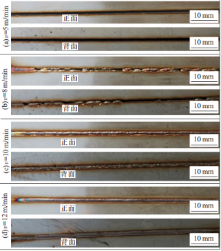
Fig.2Weldformationunderdifferentweldingspeeds
(P=100W,D=0mm)
It can be seen that the welding speed has a significant impact on forming. At low welding speeds,the linear energy of the beam is high, the metal in the molten pool evaporates strongly,and the steam reaction force generated is strong.However, the depth of the molten pool is small.Under the action of high-speed metal vapor, the liquid molten pool metal can easily rush out from the back of the deep molten hole and escape from the molten pool in the form of splash,or even the entire molten pool metal is completely ejected from the bottom. Causes the board to break.As the welding speed increases, the linear energy decreases, the evaporation reaction force generated in the molten pool metal decreases, and the impact on the molten pool metal decreases;In addition,the deflection angle of the metal plume generated in the molten pool metal becomes larger,and the evaporation reaction force is biased from the bottom of the molten pool to the rear of the molten pool, which is conducive to the improvement of weld formation.
Figure 3 shows the welding seam formation under different laser powers. The laser welding speed is 10 m/min and the beam defocus is 0 mm.It can be seen that when the laser power increases from 5 W to 1000 W, complete penetration of the 1 mm stainless steel plate is achieved,but different laser powers have a greater impact on the forming.When the laser power is 5 W, the weld width is relatively narrow, there are many burn-through holes in the weld,and there are many small spatter particles on the back.When the power increases to 50 W, the width of the weld increases and the degree of burn-through decreases.When the power increases to 100 W,the weld seam no longer has burn-through defects, and the double-sided formation of the weld seam is better at this time.
When the laser power is at 500 W, the overall weld shape is good, but a small number of burn-through holes will appear.When the power increases to 1000 W, the width of the weld continues to increase,but the number of holes caused by burn-through of the weld also increases significantly.Therefore, when the beam defocus is 0 mm, when the laser power is small or large, the sensitivity of the weld seam to burn-through is greater.Only moderate laser power can ensure good weld seam formation.This is because when the laser power is low, the volume of the molten pool is very small, and only a small reaction force of metal evaporation is required to cause the weld metal to eject from the bottom and create burn-through holes at the corresponding locations.When the laser power is high, the reaction force of metal evaporation is greater, which can easily lead to burn-through of the weld.
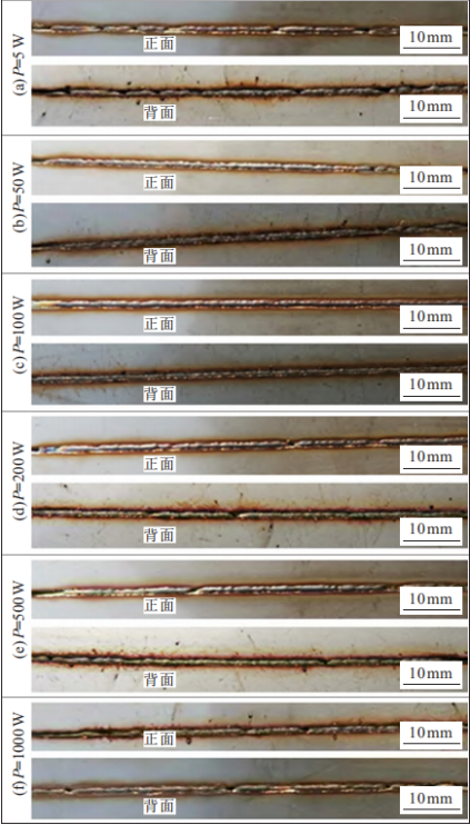
Fig.3 Weldformationatdifferentwelding powers
(v=10m/min,D=0mm)
Figure 4 shows the effect of beam defocus on welding seam formation. The results when the beam defocus is 0 mm are shown in Figures 2 and 3. Here we mainly show the results when the beam defocus is 10 and - 10 mm.As shown in Figure 4(a) and (b), when the defocus of the beam is 10 mm and the welding speed is 10 m/min, even if the laser power is increased from 100 W to 3000 W, the back of the plate cannot be welded through.Based on whether deep penetration holes are produced during the laser welding process, laser welding is divided into two modes: thermal conduction welding and deep penetration welding.There is a threshold between the two modes. Beyond this threshold, laser welding will transform from thermal conduction welding to deep penetration welding. Generally used This threshold is described as the ratio of laser power to spot diameter or laser power to spot area.Therefore, as the amount of defocus increases,the beam spot becomes larger. Under the same laser power and welding speed,laser weldingwill change from deep penetration welding to heat conduction welding, and the penetration depth will decrease accordingly.
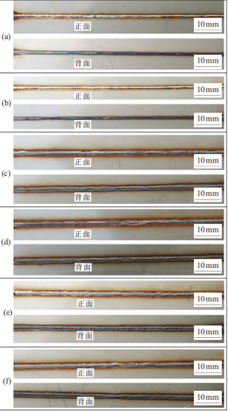
(a)P=100W,v=10m/min,D=10mm,(b)P=3000W,v=10m/min,
D=10mm,(c)P=100W,v=6m/min,D=10mm,(d)P=3000W,
v=6m/min,D=10mm,(e)P=100W,v=6m/min,D=-10mm,
(f)P=3000W,v=6m/min,D=-10mm
Fig.4 Weldformationunderdifferentdefocusingamounts
Therefore, when the defocus amount is 10 mm, the welding mode is thermal conduction welding. At this time,the weld width is large and the depth is small. The laser energy is concentrated on the surface of the molten pool and the penetration ability is limited.Therefore, penetration of the plate cannot be achieved at higher welding speeds and within a wider power range. When the welding speed drops to 6 m/min,the increase in heat input makes the weld completely penetrated, the weld width is larger, and the front and back are better formed, as shown in Figure 4 (c) and (d). When the defocus amount is - 10 mm and the welding speed is 6 m/min, the weld seam formation is also good, as shown in Figure 4 (e) and (f).
2.2Structure of welded joints
Figure 5 shows the morphology of the joint under different beam defocus amounts. It can be seen that under different processes, there are no cracks, pores and other defects in the joints. However, when the defocus amount is 0 mm, undercut defects will occur on the back of the weld, and due to the strong evaporation
of the weld metal at this time, the The disturbance in the molten pool is large, and the joint fusion line is not symmetrical on the left and right sides.When the defocus amount is 10 or - 10 mm, both the front and back sides of the weld show a convex shape, and the melting width increases.
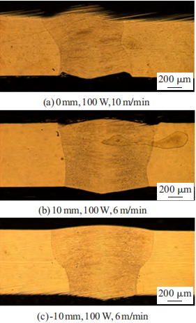
Fig.5Jointmorphologiesunderdifferentdefocusingamounts
Figure 6 shows the microstructure of the weld metal. Figure 6(a) shows the structure of the weld near the center.Figure 6(b) shows the structure of the weld close to the heat affected zone.It can be seen that the weld structure shows obvious columnar crystal growth from the edge to the center, and the grains in the
heat-affected zone of the weld do not grow significantly.

Fig.6 Microstructureof different partsofthe joint
The cooling rates of different parts of the weld and the different compositions of the weld cause the ferrite to take on different shapes, including a large amount of skeletal ferrite and a small amount of lath-like ferrite.To further observe the joint grain growth orientation and grain size distribution, Figure 7 shows the EBSD analysis of the joint. It can be seen that the base metal is composed of equiaxed grains with a grain size of 10 to 30 μm. The weld structure mainly follows the<100>direction, showing columnar growth opposite to the direction of heat flow.Most of the grain sizes in the weld area are small, with the average grain size less than 100 μm, and the rest of the columnar grains are larger, ranging from 100 to 400 μm.
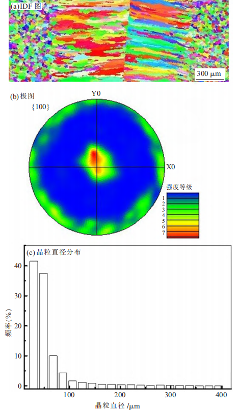
Fig.7 EBSDanalysisofjointstructure
2.3 Mechanical properties of joints
Figures 8 and 9 show the tensile strength and fracture position of the joint under different defocus amounts respectively.It can be found that when the defocus amount is 0 mm, the fracture position of the joint is the connection between the weld and the base metal, because there is an undercut on the back of the joint at this time, which easily causes stress concentration and fracture.When the defocus amount is 10 and - 10 mm, the joints are all broken in the base metal far away from the weld. At this time, the tensile strength and elongation of the joints are both high.

Fig.8 Tensilestrengthof the joint underdifferentdefocusingamounts
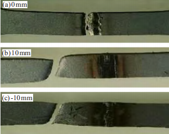
Fig.9 Fracturepositionsof the joint underdifferentdefocusingamounts
3 Conclusion
- Welding speed, laser power, and beam defocus all have a significant impact on the weld formation of 1 mm thick304 stainlesssteel sheets.As the welding speed increases from small to large, the welding seam formation changesfrom completely separated, well formed,to incomplete welding;If the laser power is too small or too large,the sensitivity of weld penetration will be greater;when the laser power is 100 W, the defocus is 0 mm,and the welding speed is 10 m/min, the weld will be formed better.The increasein the amount of defocus is conduciveto the improvement of welding seam formation, which increases the width of the welding seam,greatly reduces the sensitivityof perforation, and increases the range of welding parameters.
- The cross-sectional shape of the joint with a defocus amount of 10 and - 10 mm is good and there are no defects;The solidification mode of the weld metal is FA solidification, which is composed of austenite γ and incompletely transformed δ ferrite.Ferrite shows different shapes, including a large amount of skeletal ferrite and a small amount of lath-like ferrite;The weld structure mainlygrows columnar along the<100>direction.Most of the grain sizes in the weld area are small,and the average grain size is less than 100 μm.The remaining columnar crystals are larger in size, ranging from 100 to 400 μm.
- When the defocus amount is 10, - 10 mm, the joint has high tensile strength and elongation, and the fracture position is in the base material. However, when the defocus amount is 0 mm, the performance of the joint decreases, and the fracture positioncloseto the weld.

 EN
EN
 AR
AR CS
CS NL
NL FR
FR DE
DE IT
IT JA
JA KO
KO PL
PL PT
PT RU
RU ES
ES UK
UK TH
TH TR
TR